Maxi-Bolt
Load and Spacing Tables
Notice: Unless otherwise noted, all load and design values presented herein are based on the provisions of ACI 349-97 or earlier. Design guidance based on ACI 318-05 and ACI 349-06 is being prepared and will appear here shortly. In the mean time you may wish to review the results of cracked concrete testing performed in accordance with ACI 355.2 as called for in the new codes.
TABLE NO. 1-ALLOWABLE LOADS FOR DRILLCO MAXI-BOLTS (Pounds)
| 1/4 | 1,600 | 830 | 1,060 |
| 3/8 | 3,900 | 2,025 | 2,580 |
| 1/2 | 7,105 | 3,690 | 4,695 |
| 5/8 | 11,305 | 5,870 | 7,475 |
| 3 /4 | 16,710 | 8,680 | 11,045 |
| 1 | 30,315 | 15,750 | 20,040 |
| 1 1/4 | 50,015 | 25,980 | 33,065 |
NOTES:
1. Case 1 applicable for grouted plates. Case 2 applicable for plates in contact with concrete surface.
2. Use straight line interaction for combined tension and shear loading.
3. All load allowables are premised on the anchor's ability to develop 100 percent of the stud bolt's minimum ultimate capacity. Table No. II specifies combinations of concrete compressive strength, anchor embedment, center-to-center spacing and edge distance which will allow the anchor to develop its ultimate capacity.
4. The allowable loads noted in the above table may be assigned to each anchor in a multiple-anchor attachment. A single anchor used to anchor an attachment shall be designed for one half of the allowable loads noted.
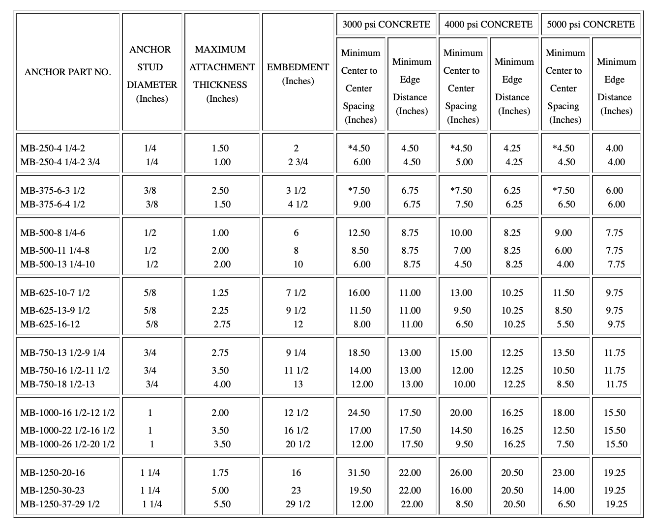
TABLE NO. II-EMBEDMENT AND CENTER-TOCENTER SPACING REQUIREMENTS FOR UP TO SIX MAXI-BOLTS IN A RECTANGULAR PATTERN

*Recommendation based on independent laboratory testing. All other embedment and center to center recommendations based on design by analysis provisions of ACI 349. Appendix B.
NOTES:
1. Maximum attachment thickness is based on torque tensioning of anchor. Any lesser attachment thickness may be used. Where the anchor is to be hydraulically tensioned, maximum attachment thicknesses will be reduced by one stud diameter.
2. Consideration of stress area reduction for limited concrete depth is not reflected in the above table. Minimum concrete depth = anchor embedment plus (center-to-center spacing/2).
3. Maxi-Bolt part numbers are specified as follows: MB-Diameter Series Number --- Overall Length-Sleeve Length (combined expansion sleeve and distance tube lengths).
4. Minimum edge distances quoted are for shear or combined tension and shear. For tension loading, edge distance may be reduced to 75 percent of given value.
5. Allowable values are limited to a maximum of six bolts in a two-row, three-column, or three-row, two-column arrangement. Allowable values may also be used for anchors placed in a single line and separated from other anchor lines by a minimum distance of two times the anchor embedment length.
6. In-place embedment length is determined by subtracting the over-all length (second number shown in Anchor Part No. column) from the exposed projection.

NOTES:
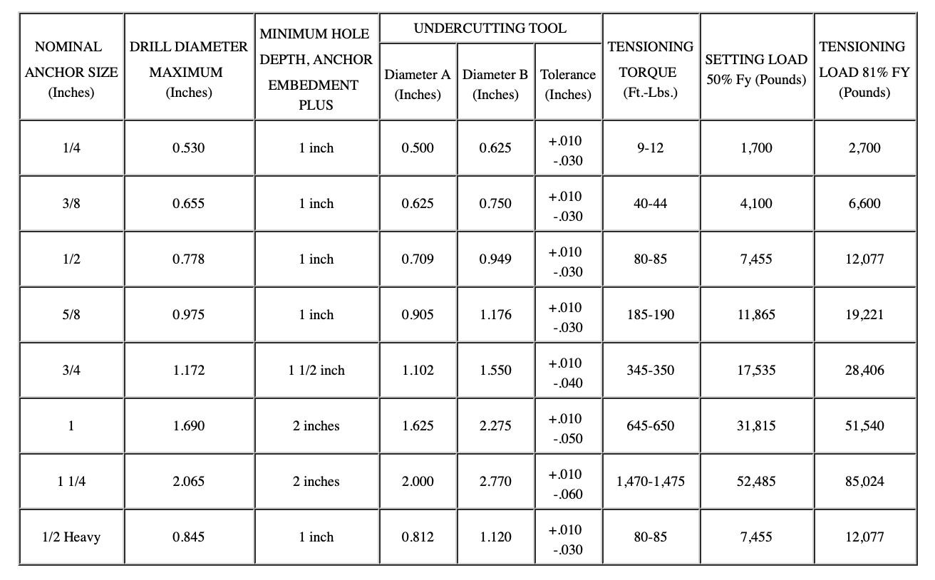
1. Undercutting tool diameter A is given for identification purposes only. No tolerance applies to this dimension.
2. Undercutting tool diameters A and B are noted in Figure No. 3
