Recommended Procedure for Installation of Drillco Maxi-Bolt Anchors
By
Drillco National Group
P. O. Box 2182
Long Island City, NY 11102
Telephone: (800) 391-0052
www.drillcogroup.com
techsupport@drillcogroup.com
1.0 GENERAL REQUIREMENTS
1.1 This procedure specifies drill sizes, minimum hole depths, embedment dimensions, and installation requirements for Maxi-Bolt anchors as manufactured by Drillco Devices Ltd.
1.2 Personnel assigned to install Maxi-Bolt anchors should receive training from a Drillco Qualified Instructor before proceeding with work.
2.0 DRILLING HOLES
2.1 Locating Holes
2.1.1 Mark placement of anchor(s) on concrete in accordance with job site specifications.
2.2 Drilling Primary Hole
2.2.1 Holes shall be drilled with a Drillco carbide percussion drill bit, Drillco "Rebar Eater" bit, or Drillco diamond core bit.
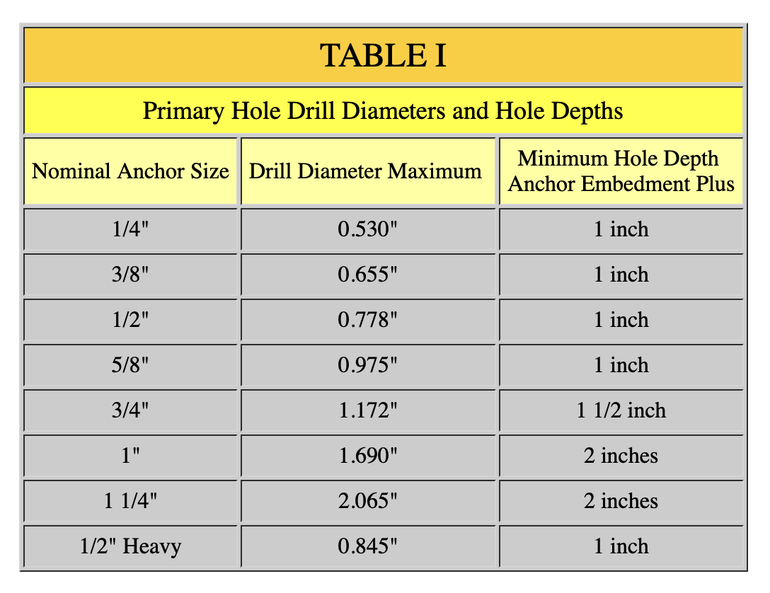
2.2.2 Drill bit diameter is specified in Table I and is presented solely for informational purposes.
a. A Drillco DBGNG (Drill Bit Go/No Go Gauge) shall be used to determine acceptability of the primary hole bit.
b. This procedure does not specify a minimum primary hole bit diameter.
2.2.3 Drill hole to depth specified in Table I.
a. Hole depth shall not be less than hole depth specified.
b. Hole may be drilled to any depth greater than hole depth specified.
2.2.4 Holes shall be drilled within 6 degrees of perpendicular to the nominal concrete surface.
a. The use of a guide, level, or square is recommended.
2.2.5 Clean hole of concrete dust and debris.
2.2.6 Measure depth of hole to ensure that minimum hole depth has been achieved.
2.3 Relocating Hole
2.3.1 If anchor must be relocated and a new hole drilled, the old hole shall be repaired in accordance with contract drawings or specifications.
2.4 Drilling Undercut in Primary Hole
2.4.1 Undercut in primary hole shall be drilled only with a Drillco Undercutting Tool.
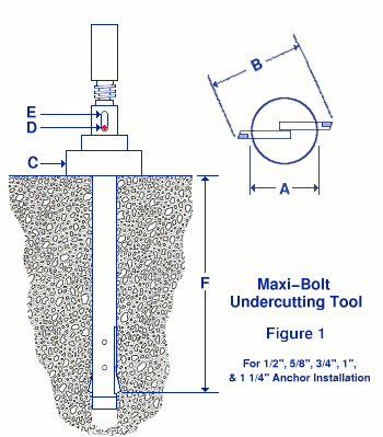
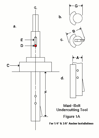
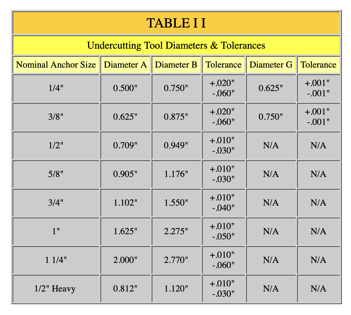
2.4.2 Tool diameter A and cutter diameter B (diameter with cutter(s) in fully opened position) are specified in Table II (for informational purposes only) and illustrated in Figures 1 and 1A.
a. A Drillco UTGNG (Undercutting Tool Go/No Go Gauge) shall be used to determine that the cutter blades are within the tolerances specified in Table II.
2.4.3 The depth at which the undercut is formed is controlled by the position of tool's bearing sleeve (C in Figures 1 and 1A). To achieve the correct undercut depth:
a. Set tool's bearing sleeve so that Dimension F in Figure 1 or 1A corresponds to the specified embedment depth of the anchor being installed.
b. When anchors are to be installed prior to placement of attachment, the bottom of the bearing sleeve should be placed in contact with the surface of the concrete.
c. When anchors are being installed through an "in place" attachment, the bearing sleeve should be placed in contact with the surface of the attachment. Furthermore, the attachment should be in contact with the nominal surface of concrete.
2.4.4 With the bearing sleeve in contact with the surface of the concrete or attachment, but with no pressure applied to the drill, start drill motor.
2.4.5 With drill motor running apply a steady pressure on the drill.
2.4.6 When Pin D is in contact with bottom of Slot E (as shown in Figures 1 and 1A) the undercut is complete. To verify this it will be necessary to stop the drill motor and observe the pin location.
2.4.7 After the undercut is complete, stop the drill motor and remove the tool from the hole. Inspect insert blade(s) to ensure that they have not been damaged during the drilling operation.
2.4.8 Clean the hole of concrete dust and debris.
3.0 INSTALLING ANCHORS
3.1 Examine Assembled Anchor
3.1.1 Check to ensure that all components are present and that the bolt is correctly assembled. See Figure 2.
3.1.2 No modification to the anchor shall be permitted.
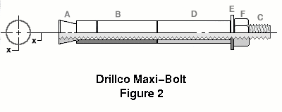
| A | Conical Nut |
| B | Expansion Sleeve |
| C | Threaded Stud Bolt |
| D | Distance Tube |
| E | Washer |
| F | Heavy Hex Nut |
| Plating | Non Stainless Steel Bolts come standard with plating to specification ASTM B633 SC1 Type II |
3.2 Setting Anchor
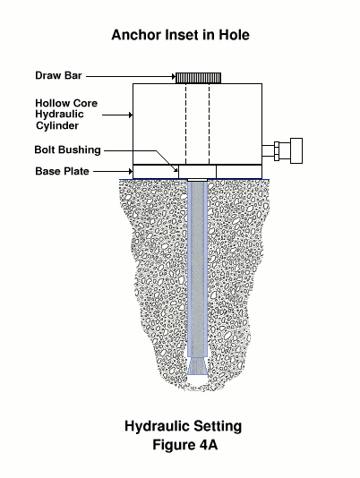
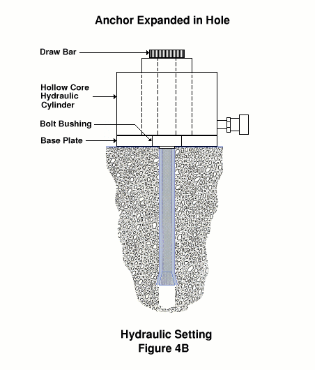
3.2.1 To set the Maxi-Bolt it is necessary to draw the conical nut on the stud bolt up into the anchor's sleeve. In so doing the expansion sleeve will be forced to move laterally into the undercut portion of the hole and the conical nut will seat fully inside the expansion sleeve. See Figure 4B. This process may be accomplished in one of three ways. (Note: Figure 4A shows hydraulic setting and Figure 6 shows the Hand Bolt Setter.)
3.2.2 Manual Setting
3.2.2.1 Remove nut and washer from anchor and place the end of the anchor stud bolt through the center hole of the Bolt Bushing (from Figure 3). The Bolt Bushing should be oriented so that the 1/16" offset bears against the anchor sleeve. Finger tighten hex nut and washer on anchor bolt assembly.
3.2.2.2 Insert anchor into properly drilled, undercut and cleaned hole.
3.2.2.2.1 Because of close tolerance between conical nut O.D. and hole I.D. it may be necessary to lightly hammer the anchor into the hole:
a. If hammering is necessary, steps shall be employed which will prevent damage to the threads of stud bolt.
3.2.2.3 Depending on the end configuration of the stud bolt, use an allen wrench or adjustable wrench to hold the stud stationary while the heavy hex nut is tightened. The heavy hex nut should be tightened until the conical nut is seated and the expansion sleeve contacts the I.D. of the conical undercut in the concrete. The installer will note a sudden increase in torque required at this point. During the setting operation the orientation of the bolt bushing should be observed and should not be allowed to rotate relative to the concrete surface.
3.2.3 Setting Anchor with Hand Bolt Setting Tool
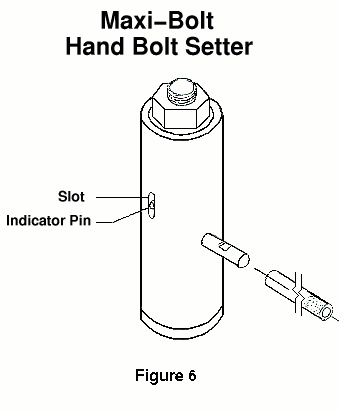
3.2.3.1 Remove hex nut and washer from Maxi-Bolt. Thread anchor stud into the bottom of the Hand Bolt Setter so that anchor sleeve is firmly in contact with the 1/16" offset of the Bolt Setter's bolt bushing. Place assembly into clean undercut hole. Grasp Hand Bolt Setter handle and turn hex nut in a clockwise direction using a 1 5/8" box end wrench or adjustable wrench. When pin is within 3/16" of the top of slot and the torque required to turn the Hand Bolt Setter hex nut has increased considerably, the anchor is set. Loosen hex nut. Remove Hand Bolt Setter by rotating it in a counterclockwise direction. See Figure 6.
3.2.4 Hydraulic Setting
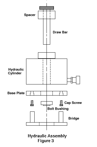
3.2.4.1 Check to insure that components required for hydraulic setting are present and assembled. See Figure 3.
3.2.4.2 Remove nut and washer from anchor and place the end of the anchor stud bolt through the center hole of the Bolt Bushing. The Bolt Bushing should be oriented so that the 1/16" offset bears against the anchor sleeve. Position the Bolt Bushing in the center of the Base Plate. Then attach draw bar to the stud bolt as shown in Figure 4A.
3.2.4.3 Place the anchor into the drilled and undercut hole so that the Base Plate on the hydraulic cylinder is in contact with the surface of the concrete or attachment. Load the bolt to the values specified in Table III. (Table III gives values for A193 Grade B7 material. For other materials see the Tables for Other Materials.) Remove the Draw Bar, Hydraulic Cylinder, and Bolt Bushing from the anchor.
3.3 Tensioning Anchor
3.3.1 Torque Tensioning
3.3.1.1 Torque anchors to the values specified in Table III. (Table III gives values for A193 Grade B7 material. For other materials see the Tables for Other Materials.) For torquing of 1/4" Maxi-Bolt anchors it is suggested that a click or breakaway type torque wrench be employed to insure that the maximum torque is not exceeded.
3.3.2 Hydraulic Tensioning
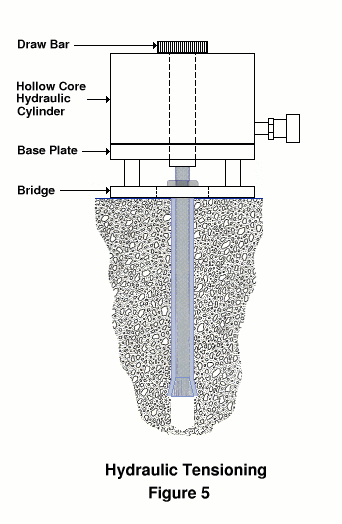
3.3.2.1 Replace and finger tighten nut and washer on anchor stud bolt. Place a center pull hydraulic cylinder over the anchor stud and bridge cylinder so that it leaves the hex nut exposed and bears on the concrete surface or attachment around the anchor. Turn the draw bar down onto the anchor and tension it to the values specified in Table III. (Table III gives values for A193 Grade B7 material. For other materials see the Tables for Other Materials.) Tighten down the hex nut to retain the load. Release the pressure and remove the hydraulic cylinder. See Figure 5.
For Setting and Tensioning Loads with Data for Drillco Supplied RC-Series Cylinders see Table III (RC Data)
For Setting and Tensioning Loads with Data for Drillco Supplied RCH-Series Cylinders see Table III (RCH Data)
