Case Study in the Use of Very Large Diameter Drillco Maxi-Bolts
Synopsis: Spurred by the needs of a large steel producer for 160mm (6.3 inch) and 4 inch diameter post-installed anchors, Drillco designed, fabricated and delivered these very large diameter Maxi-Bolt anchors which were used to anchor new roughing mill pinions and gear boxes at the company's Alabama plant.
Facility: Steel Rolling Mill
The plant produces flat-rolled steel for appliances, pipes and tubes, construction, automotive and other industries.
Location: Alabama
Job Description: Install new gear box pinions for roughing mills.
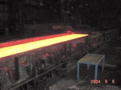
As part of the manufacturing process molten steel is continuously cast and then rolled to a smaller cross section while still hot. It is the function of the roughing mill to begin this process and then deliver material to finishing mills which further modify the cross section of the steel until the desired dimensions of the end product are achieved. In the picture to the right the thickness of the steel has been reduced to about four inches. The four inch thick slab is conveyed on rollers. It is the function of the gear boxes and pinions to transmit power from an electric motor to the rolling line.
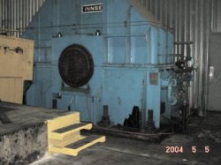
Since the footprint of the new equipment did not match that of the old, the existing concrete anchors could not be re-used. Rather than demolishing the existing foundations and then pouring new foundations with new concrete anchors, the client decided to re-use the existing foundations and use post-installed anchors for the new gear boxes. One of the existing gear boxes can be seen
Client's Anchorage Investigation and Conclusions:
The client researched available post-installed anchor types and determined that there are three types of concrete anchors as classified by the failure mode in load-to-failure testing.
-
Slip Critical
The first type is a slip critical failure anchor in which the allowable load is based on how much force the anchor can develop prior to slipping out of the drilled hole in concrete. Often the slip is followed by a shallow concrete spall once the anchor's embedment has been reduced sufficiently. Slip critical anchors can be either mechanical friction anchors or grouted/epoxy anchors. Often, grouted/epoxy anchors will display a bond failure between the anchor steel and grout/epoxy or between the grout/epoxy and concrete with resulting anchor slip. The load at which slippage occurs typically displays a high degree of variability and, as a result, good engineering practice requires large safety factors for these anchor types. The loads at which epoxy/grout anchors will fail are also highly suseptable to installation conditions, e.g. moisture in the drilled hole and hole cleanliness, as well as cracking of the concrete.
-
Concrete Failure
The second type displays a concrete failure mode. This occurs when the concrete fails in tension creating a cone shaped spall.
-
Steel or Ductile Failure
The third failure mode is called a ductile failure. Anchor steel tensile failure can be reliably achieved when there is both a positive, bearing transfer of anchor loads into the concrete and the anchor embedment is sufficient to develop the full capacity of the steel.
Of the three anchor types, the most desireable is the steel/ductile failure anchor.
-
The strength of steel is well defined and repeatable permitting moderate safety factors, and
-
If an overload occurs, steel will yield and stretch before breaking, absorbing energy from the load as it does so.
The Client's Design and Installation Concerns:
The new gear boxes and pinions at the client's roughing mill required a larger footprint and new concrete anchors had to be installed. Their initial anchor design required drilling 12 inch diameter holes 48 inches deep in the concrete. The anchor bolt consisted of a 160mm (6.3 inch) diameter, A36 all-thread rod with a nut on the end. The rod and nut were to be placed in the 12 inch diameter hole and then the hole was to be filled with epoxy. Even though epoxy appeared to be the only solution, they felt that the application of holding a pinion stand down in a roughing mill required more positive securing. The longevity of any foundation, especially one in such a severe application, is obviously of concern. The demanding application combined with a tight time line for execution of the project caused the team to seek alternatives. It was decided that a ductile anchor should be used if at all possible.
The Solution:
The client was aware of Drillco Maxi-Bolt ductile anchors, but knew that they had only been manufactured up to 1 1/4 inch (approx. 30mm) diameter. They nonetheless contacted Drillco about supplying 160mm diameter Maxi-Bolts. Drillco agreed with their philosophy that there are “No Boundaries Only Challenges” and was commissioned to engineer and fabricate the anchor. Because there had never previously been a Maxi-Bolt of this size, a prototype was manufactured and tested along with the undercutting tool required for setting the anchor bolt.
The Prototype Trial:
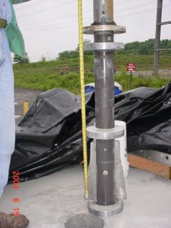
A monolithic cube of 4,000 psi concrete some six foot on a side was poured mid April of 2004 and allowed to fully cure. In mid June the anchor and tooling were set up to install the test bolt. The following photographs illustrate both the size of the Maxi-Bolt and its method of installation.
The trial started just after 8 am and was completed by 11:30 am.
A 9 inch diameter hole was drilled in the concrete test block to a depth of approximately 45 inches. The hole was then undercut using the flaring or undercutting tool. As can be seen in the photo, the undercutting tool can be lowered into the hole in concrete until the larger ring near the top of the tool contacts the surface of the concrete which prevents it from further travel.
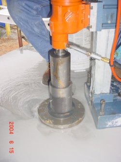
The undercutting tool after it has been lowered into the hole. Downward pressure of the drill motor forces the two cutting blades to rotate outward, creating a bell shaped enlargement toward the bottom of the hole. In the section of the undercutting tool below the orange drill motor and above the concrete, a pin travels in a slot in the tool indicating how far laterally the cutting blades have rotated. Once the pin has reached the bottom of the slot, the undercutting operation is complete and the tool may be withdrawn from the hole.
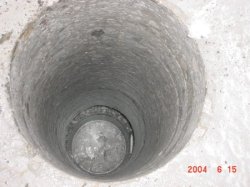
After vacuuming the water from the hole, the photo at the right above shows the undercut near the bottom of the hole. Notice the reinforcement bars that were cut during the installation.
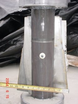
A closeup view of the flaring tool used to make the undercut. Notice the width of the undercut. The blades are renewable and coated with diamonds. The flaring operation took some 20 minutes which included cutting a reinforcing bar at the bottom of the undercut.
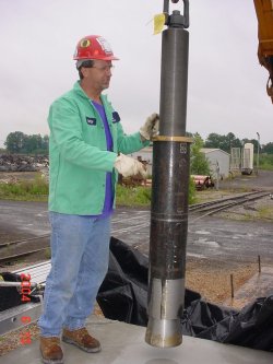
160 mm anchor prior to placement in core drilled hole.

160 mm anchor installed in the core drilled hole. The next step will be to set the wedge in the undercut section of the concrete.
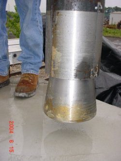
This picture shows a closer detail of the actual mechanical securing wedge. While the sleeve of the anchor is held flush with the surface of concrete, the threaded bolt and attached cone are pulled up into the anchor's sleeve bending the sleeve laterally into the undercut area of concrete.
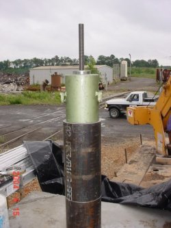
Hydraulic ram used to pull the threaded bolt and cone up into the undercut area of concrete.
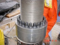
Due to the extreme size of the anchor, it was decided to use a nut called a “superbolt”. The large nut is screwed down on the anchor bolt and then each small, individual bolts around the circumference of the nut is torqued, reacting against the sleeve and developing the required tension in the anchor bolt.
Plant Installation:
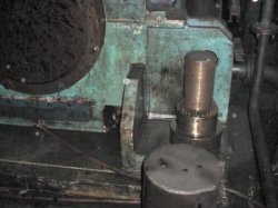
Four 160mm and eight 4" diameter Maxi-Bolts were used to anchor the roughing mill pinion and gear box at the Alabama plant. The 4" diameter Maxi-Bolts had a 6 5/8 inch diameter sleeve, an overall length of 76 inches and a sleeve length of 60 inches. The 160mm diameter Maxi-Bolts had a 9 inch diameter sleeve, an overall length of 89 inches and a sleeve length of 49 inches. Shown at left is one of the installed Maxi-Bolts.
